Impedancia LW antény
http://www.w8ji.com/end-fed_1_2_wave_matching_system_end%20feed.htm
|
End fed longwire or random wire antenna End Fed Half Wave or "end-fed dipole" AntennasEnd-fed halfwave antennas were once very popular. Reviewing old antenna books and amateur magazines, longwires and Zepps were popular antennas. After WWII coaxial lines became readily and cheaply available. Center fed dipole antennas appeared, with coaxial feeders that could be easily and safely routed into the house. Popularity of end-fed antennas faded as coaxial-fed antennas became mainstream. End-fed antennas are increasingly popular again, at least partly because of compact iron toroid cores. Small soft-iron cores allow compact, easy-to-build, low-power transformers and networks. The combination of lightweight compact matching systems, combined with the installation convince, visual appeal, and installation simplicity of NOT hanging a heavy coaxial feeder from a long span of thin antenna wire, has rekindled interest in end-fed half-wave antennas. Unfortunately end-fed antennas have also come back with a little misconception. One commonly repeated myth or "theory" is that half-wave antennas, being resonant, do not require a counterpoise. Lack of a proper counterpoise does not mean the antenna will be worthless and not make contacts, it simply means something else replaces the missing counterpoise area. The feedline, as well as everything connected to and surrounding the feedline, becomes part of the radiating system. This creates three potential problems: 1.) The feedline, mast, and things around the feedline connect into the receiver. This brings noise into the receiver. 2.) The feedline, mast, and things around the feedline become part of the radiator. This brings voltage (electric fields) and current (magnetic fields) directly into the shack. 3.) The feedline and grounding affects SWR and tuning. Since we often do not have a baseline for noise, unnecessary additional noise will often go unnoticed. The remaining two issues are more likely to be noticed, but only if we run enough power to cause RF burns, power supply shutdown, or other forms of RFI. Transmitter power levels, feedline length and routing, and the susceptibility of equipment to RF problems greatly influence things we most likely notice. This is why some people (usually with QRP power levels) swear by end-fed half-waves, while others (usually with higher power) avoid end-fed antennas. The reason for that is simple, end-fed half waves have common mode feedline current problems affecting their performance, and these common mode currents cause inconsistency in user satisfaction. End-fed half wave antennas are best for temporary antennas using low power and batteries, far from power mains and noise sources. They are more prone for problems near noise sources or consumer gear, and can easily exceed FCC RF exposure limits with surprising low power levels. In nearly all cases, if we notice it or not, an inadequate counterpoise hurts antenna pattern and efficiency. This is why high power stations often have more efficient, more ideal, antenna systems. Higher power very often excludes use of power wasting systems, because the wasted power often creates significant local problems. If 5% of 10 watts is exciting the desk with RF, it isn't any big deal. If 5% of 1500 watts excites the desk with RF, the result can be hazardous. Styles or Types of EFHW Antennas There are four basic styles or types of end-fed half wave antennas:
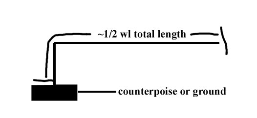
The five styles above share one common trait. Absent a counterpoise of some type and proper care in feed system construction, the feed methods above can induce significant common mode currents on the feed system. This means they are subject to feedline radiation and "RF in the shack", including increased TVI/RFI and receiving system local noise pickup. The actual severity of feed system common mode currents in some systems may surprise many of us, while the lack of problems in other combinations can be equally surprising. Low power, long feedlines, or even just a lucky length of feedline or counterpoise can hide common mode transmitting problems, even if unnecessary receive noise ingress is more difficult to determine. Two configurations, sometimes called "end-fed dipoles", are often the worse of the end-fed systems. We'll see why, as we analyze each type. Direct end-feed or traditional longwire style antenna with operating position matching networkThe direct end feed antenna brings the end of the halfwave to a transformer or lumped component network of some type. The network is connected to something it "pushes" against so current can be forced into the antenna. The basic inverted-L antenna system or "half-wave longwire antenna" looks like this:
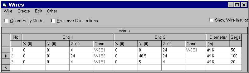
We can calculate end-impedance of this antenna with Eznec. The model is:
Wire 1 is the vertical length, 20 feet. Wire 2 is the horizontal length, 46.5 feet Wire 3 is the small counterpoise, 5 feet
With 100 watts applied, current distribution of the antenna is: Wire 2, horizontal wire 47.5 ft long 24 ft high
Wire 1, vertical wire 20 ft long
Wire No. 3 counterpoise 5 ft long 4 ft high:
The feedpoint impedance (the little circle by the 3 on the antenna view) is:
The problem with this system isn't so much the current and resulting magnetic field surrounding the antenna feedpoint. The dominant problem is the extreme voltage and resulting intense electric field surrounding the antenna feedpoint. With only 100 watts, the antenna feedpoint has several hundred volts. That voltage substantially increases at the counterpoise's open end. As a matter of fact, the open end of the counterpoise wire has almost 3,000 volts of peak voltage with only 100 watts of applied power!! One commonly repeated myth claims end-fed half wave antennas, being resonant antennas, do not require a counterpoise. We see above, end-impedance is not infinite. In this case it is a few thousand ohms. Because end-impedance is finite, ground currents still flow with a perfectly resonant end-fed. Changing frequency 10%, which is equivalent to a 10% antenna length error, we can observe a ground current increase:
At resonance we had:
Being 10% off-resonance more than doubles current. That is a large current increase, and it shows an advantage in having a resonant half-wave antenna, but even at resonance end-current is not zero! Any claim perfect resonance eliminates requirements for a counterpoise is not correct. A 10% length error more than doubled common mode feedpoint current, but current was never zero to start with. This is actually common sense, because the end impedance of a 1/2 wave antenna is not infinite. If end-impedance was infinite, we could never manage to apply power. The end-impedance of any half-wave is finite, and varies with antenna diameter, length, and surroundings. Thin wires have higher impedance, thick antennas have much lower end-impedance, and losses in surroundings tend to further reduce end-impedance. Moving 5% in frequency:
With a 5% length error from resonance, we now see only an 18% increase in current. That's negligible since many other things we might do (like moving the antenna a few feet in height) would make a much larger change.
There is merit to maintaining resonance because current is at a minimum value, but we only need to worry when resonance errors are somewhat large. When length errors are modest (under 5%) the error has only a small effect on ground current. The reason for this is simple. The reactance or lack of resonance isn't what determines current, the resistive part of the impedance does. We are looking for a resistance peak in the end-impedance of the antenna...not necessarily resonance. The source impedance's resistive part was 3300 ohms at resonance. At 5% length error it was still 2382 ohms. With 10% error, the resistive part of impedance was under 1000 ohms. With the non-resonant antenna, voltage is 925 volts instead of 575 volts. Electric fields increase around the feedpoint. RF voltages (the electric field) can be a major issue with end-fed longwire antennas, resonant or not. Also see this link: End fed longwire or j-pole antenna
Very Short or "Missing" CounterpoisesIf we truncate a counterpoise, we greatly increase voltage on the counterpoise and the side of any matching system connected to the counterpoise. Voltage increases enough to allow the "countering" current to flow into whatever is around the feedpoint, including the feedline, as displacement or conducted currents, or a combination of the two. The fact the feeder becomes involved does not mean the antenna will abruptly stop working. A seriously truncated counterpoise just means the system is ripe for increased feedline common mode problems. Let's look at the feedpoint area of a 40-meter half-wave antenna with a short counterpoise. In this case the antenna is 66.4 feet long, the "counterpoise" is 6 feet long, and the feedline (wire 3) is 32 feet long:
The round circle is the source, and the square box represents a 10 pF stray capacitance from the feeder across the transformer to the counterpoise. We have the following 100-watt currents:
Wire 2 short counterpoise .08076 amperes Wire 3 vertically oriented feedline .06634 amperes With just 10 pF stray capacitance from primary to the counterpoise side of the transformer, we have 82% of counterpoise current flowing into the feeder.
Feed impedance seen by the matching transformer secondary in the system above is:
There is no question this system will radiate, but there is also little doubt the conductor we assumed was a counterpoise is not the only counterpoise. If we remove the counterpoise we have the following feed impedance and feedline common mode:
This shows the extreme difficulties in isolating the feeder from the antenna when a counterpoise is very small, even with a half-wave antenna. Just 10 pF of stray capacitance at the feedpoint results in significant feedline current. There is more about counterpoises on this counterpoise page
What else affects Antenna Impedance?From above we see higher antenna resistance is a good thing for current, and precise length is not overly-critical so far as affecting counterpoise current. We also see lower reactance is a good thing for voltage, and length can affect voltages (and the electric field) surrounding the antenna and counterpoise near the feedpoint. What about a thicker antenna? With a 1" thick antenna 7 MHz impedance becomes 1684 - J 716.3 ohms and resonance is well below 6 MHz. The reactance problem is because the counterpoise is too short. The drastic resistance reduction at peak resistance occurs because the wire is thicker. Obviously a thicker antenna has higher ground or counterpoise currents! (Half-wave broadcast towers often have feed impedances under 800 ohms at resonance. ) What about antenna surroundings? As the area around the antenna becomes more cluttered and/or has more power loss, antenna end-resistance is reduced! Over perfect ground the antenna end-impedance almost doubles from that over average ground. Over lossy ground, especially when the antenna is low in height, feed resistance decreases even more. (End-fed 1/2 wave feed impedance decreases, while center fed half-wave antenna impedance increases with added loss!) With a small counterpoise and end-feed we need to:
Longwire ImprovementsThe best solution I can think of to common mode or "RF in the shack" problems with this form of antenna is to isolate the counterpoise or antenna ground from the station feed. At low power levels a simple link coupled matching network is a good solution, provided the secondary has no RF path to station equipment. One way to accomplish this is by using link coupling with two floating antenna terminals.
U1 goes to antenna U2 goes to counterpoise, do not connect counterpoise to station ground
In the circuit above for a tightly coupled link:
Assume we have a 5000 ohm load and 50 ohm rig, with perfect mutual coupling between windings. The turns ratio of T1 is sqrt of 5000/50 or a 10:1 ratio. The reactance of C1 at 3/4 mesh (so you have adjustment range) should be 5000/10, or 500 ohms. This is a loaded Q of ten, you need LESS Q with lower transformation ratios and more Q with higher ratios or the circuit becomes too sharp (with excessive voltages and currents) or too "mushy" (we would not be able to correct reactance issues) to have a good "tune feel". The reactance of L1 secondary should be 500 ohms in this example. U1 should connect to the antenna, U2 to the counterpoise or ground which should NOT connect to the station equipment. The counterpoise should be as long and straight as possible, and directly under the antenna if possible. Ideally the counterpoise, if less than 8 wires 1/4 wl long, should be elevated and insulated from earth. Do NOT make the counterpoise longer than 1/4 wl, especially if it is only a single wire! Most of us, since this is a temporary or compromise antenna, will use a very small ground system. I've found connecting a counterpoise to earth, say a ground rod, actually reduces antenna efficiency. If you run low power and don't have a ground or counterpoise, you might just connect U2 right back to the coax shield from the radio. This way you can use the capacitance of the radio and station wiring as a ground system. There is always some cut and try in this, because mutual coupling is not perfect and there are stray reactances. PAR Antenna and other so-called End-fed Half-waves or end-fed dipolesMany antenna designers and experimenters assume we can end-feed a half-wave without creating potentially significant feedline common-mode currents. The antenna view below shows common mode currents in a feedline grounded 3/4 wl away from a perfectly resonant end-fed 1/2 wl antenna:
Currents are shown below. I fixed the power level at 100 watts. The following are the current minimums and maximums: --------------- CURRENT DATA --------------- Maximum antenna current is .758 amperes, while the coax common mode current maximum is actually 1.02 amperes! It is actually possible to have MORE radiating current at the common mode current maximum in the feedline than in the antenna itself. This is because standing waves on the OUTSIDE of the cable transforms voltage and current. (This has nothing to do with standing waves INSIDE the feedline that an SWR meter measures.)
That was worse case feedline length. Now here is best case feedline shield grounding:
--------------- CURRENT DATA --------------- Now we see the current maximum in the antenna is 1.12 Amperes, while the undesired radiation current maximum in the feeder is 0.219 amperes. The antenna now radiates considerably more power more than the feedline. This is a good thing since we usually want the antenna to radiate more than the feedline! This problem doesn't mean the end-fed antenna won't work or is a bad antenna. It does mean that the feedline is a part of the radiating system, and how the feeder is routed and grounded will drastically affect system performance.
It is electrically impossible to end-feed a 1/2 wl antenna without a good counterpoise at the feedpoint and have a totally "cold" feedline. A ten-turn choke or normal current balun at the feedpoint certainly won't change anything. The only way to minimize common mode on the feedline is to pick the "lucky feedline length" or feedline grounding point. If you don't want the feedline to radiate, center feed the dipole and use a proper feedline length of a good current balun.
To read more about end-fed antennas, follow the end-of-page links: |