16F628 PWM LED test
http://www.bristolwatch.com/PIC16F628A/a6.htm
PIC16F628 Pulse Width Modulation Controls Brightness of LED
For how to calculate frequency and duty cycle for PIC PWM
see Working with Pulse-Width Modulation and the PIC Microcontroller
;********************************************************************** ;Filename: pwmdemo1.asm ;Uses PIC16F628A ;Date: 13 Nov. 2013 ;Author: Lewis Loflin ;http://www.bristolwatch.com ;Uses PWM to control LEDs from off to bight to off again ;Demonstrates the use of loops and PWM ;Delay routines based on 16 mHz external ; ;PWM Period = [(PR2) + 1] * 4 * TOSC * (TMR2 Prescale Value) ;PWM duty cycle = (DCxB9:DCxB0 bits value) * ; Tosc * (TMR2 prescale value) ;Tosc = 16 mHz / 4 ;PWM output PORTB, 3 ;********************************************************************** list p=16f628A ; list directive to define processor #include; processor specific variable definitions errorlevel -302 ; suppress message 302 from list file __CONFIG _CP_OFF & _LVP_OFF & _BOREN_OFF & _MCLRE_OFF & _WDT_OFF & _PWRTE_ON & _HS_OSC ; Use _INTOSC_OSC_NOCLKOUT for ; internal 4 mHz osc and no ext reset, use pin RA5 as an input ; Use _HS_OSC for a 16 mHz ext crystal. ; Use _XT_OSC for 4 mHz ext crystal. Page 95 in spec sheet. ;------------------------------------------------------------ cblock 0x20 ; Begin General Purpose-Register ;-------------------------- counters count1 count2 count3 val endc ORG 0x000 ; processor reset vector goto setup ; go to beginning of program setup ; init PIC16F628A movlw 0x07 ; Turn comparators off and enable pins for I/O movwf CMCON clrf INTCON clrf T2CON clrf TMR2 banksel TRISA ; BSF STATUS,RP0 Jump to bank 1 use BANKSEL instead clrf PIE1 movlw d'255' ; frequency ~ 1000 Hz movwf PR2 clrf TRISA clrf TRISB banksel INTCON ; back to bank 0 clrf PORTB clrf PORTA movlw b'00000111' movwf T2CON ; turn on TMR2 prescale 16 movlw d'0' ; duty cycle = 0% or no output movwf CCPR1L movlw b'00111100' movwf CCP1CON ; turn on PWM goto main main ; first loop increases brightness of LEDs clrf val ; val = 0 gg call delay_100ms movf val, w movwf CCPR1L ; output val to pwm RB3 movlw d'10' addwf val, F ; add 10 to val btfss STATUS, C ; check for carry goto gg ; no carry loop again ; decreases brightness of LEDs movlw 0xFF movwf val hh call delay_100ms movfw val movwf CCPR1L ; save val to register movlw d'10' subwf val, F ; subtract 10 from val save in val btfsc STATUS, C ; check for < 0 goto hh ; no loop again clrf CCPR1L goto main delay_1ms ; 16 mHz crystal, 4 mS with 4 mhz crystal movlw 0x07 movwf count1 aa movlw 0xBC movwf count2 decfsz count2, F goto $-1 decfsz count1, F goto aa return delay_100ms ; 16 mHz crystal, 400 mS with 4 mHz crystal movlw d'99' movwf count3 bb call delay_1ms decfsz count3, F goto bb return END ; directive 'end of program'

- Projects using PIC16F628:
- Home Built PIC16F628 Prototyping Board
- Exploring the Microchip PIC in Assembly
- Using a Microchip PIC with TLC548 Serial ADC
- Controlling PIC Pulse Width Modulation with a Serial ADC
- Using TMR0 on a PIC with Interrupts
- External Clock Crystal with PIC16F628 TMR1 Generates Interrupt
- PIC Using Rotary Encoder to Operate Stepper Motor
- PIC16F628 Pulse Width Modulation Controls Brightness of LED
- Another way to Turn On-Off PWM in a PIC
- TLC548 Serial ADC Spec. Sheet
- You Tube Videos for the Series
Related Videos, Links
- Using the MAX7219 with the 18F2550 Programs:
- MAX7219 Display Driver and a PIC Micro Controller
- MAX7219 Display Controller in the Non-Decode Mode with PIC
- YouTube Videos:
- My YouTube Channel
- MAX7219 display controller with 8X8 LED Matrix
- Programming the MAX7219 and 7-Segment Display
- Schematics and drawings:
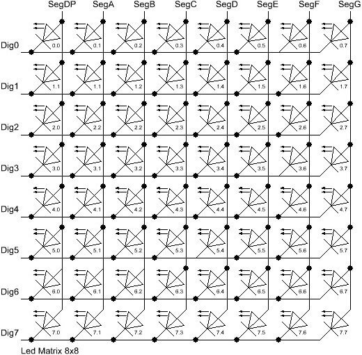
- LED Matrix diagram
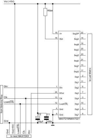
- Connections to MAX7219
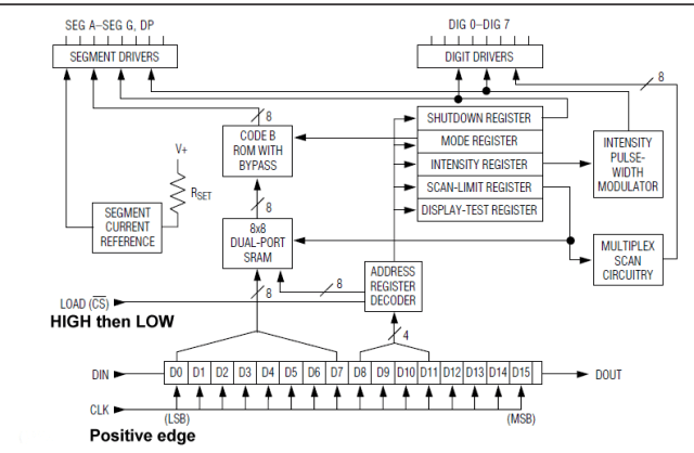
- MAX7219 internal block diagram
- Using Hall Effect Sensors with Alternating Current
- Using Hall Effect Switches and Sensors
- Using Ratiometric Hall Effect Sensors
- Using Hall Effect Sensors with the Arduino-ATMEGA168
- TL173C 12-Volt Ratiometric Hall Sensor (PDF file)
- UGN3503 5-Volt Ratiometric Hall Effect Sensor (PDF file)
- SS466 Hall Latch (PDF file)